
Only thing to note is to check qmk docs if the screens controller is supported by default. If it is, it’s easy. If not it takes more work.


Only thing to note is to check qmk docs if the screens controller is supported by default. If it is, it’s easy. If not it takes more work.


Yes you can. But you have to address the rgbs as a true matrix which is a fair bit more work.


I just used all my budget on prototypes. Sigh.


Actually, I prefer liftoff


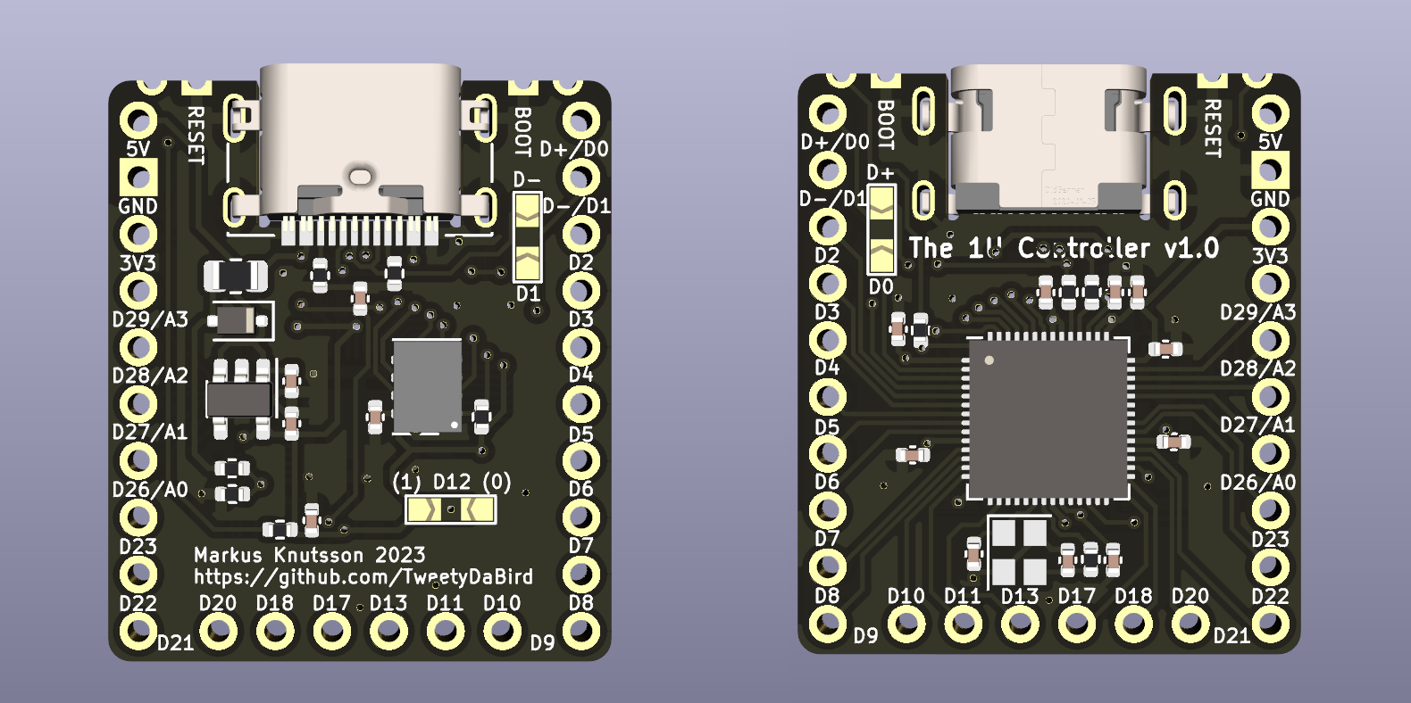
It should, at least as long as we are talking about choc switches on an MX spacing, or a dual footprint design, as the pin headers are spaced for that. Otherwise there will probably be interference, or very, very close to it at least.


 How about this then? (No promises on signal integrity of that USB signal, we are pushing limits)
Just keep in mind, that placing the controller not at an edge, will likely make the USB port interfere with the next socket, it’s not really meant for that. Meaning you should probably de-solder the port then. Also, by powering through the 5V/GND pins, you negate the VBUS detection, and there simply aren’t enough pins/space to break that out as well, so it’s a compromise.


I wasn’t planning on it since sacrifices two pins.
And seeing as the USB port is available to place by the edge very easily as you can place the controller over any key.
To explain, the USB port should end up needing only 3-5 mm edge on a sandwich case, or a hollow similar to how most pcb’s place it on a CNC/3d case.
Any particular reason beyond that? I’m open to reasonable compromises.
Btw, I can easily pull them out to a pair of pads, there is space for that.


That’s not he projected range shown on the display. That’s the actual range the battery will give you.
They temporarily removed a bit of the safety margin built in to reduce battery wear, allowing people to get out of harms way without a stop to charge if they were on the limit. But only for people moving away from The affected area, etc. so smart and helpful.
Try the Lotus 58. You get a bit more options over all.